TM 5-3805-263-14&P-1
21.
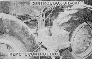
Remove the two bolts and straps securing the
remote control box to the front frame. Remove
its
cover
and
store
in
the
operator’s
compartment.
22.
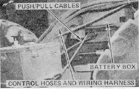
Slide the arm of the remote control box
assembly into the bracket next to the left hand
battery box. Remove the dust covers from the
cables and hoses. Connect the hoses and
wiring harness to the connection panel on the left
frame rail. Route the three (3) mechanical
push/pull cables under the battery box as shown,
toward the front of the rear frame. Use the
identification tags to connect the cables to their
appropriate counterpart emerging from the front
of the rear frame.
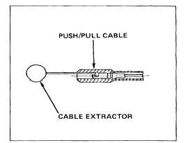
NOTE
The controls on the remote control box may
have to be adjusted to make the cable
connections. If necessary, use the cable
extractor tool 5R7047 to extend the cables.
23.
Start the engine and apply a slight amount of
blade down pressure, then drive the rear frame
very slowly about three (3) feet from the front
frame. Guide the jumper hoses carefully to
prevent damage. See page 13, Remote Control
Operation, for proper operating procedures.
24.
Disconnect the electrical jumper cable and
jumper hoses and install the dust caps.
25.
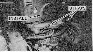
Install the auxiliary engine drive yoke guard and
strap the hoses to the tandems and the
articulation cylinders to the top of the rear frame.
105