TM 5-3805-263-14&P-1
13.
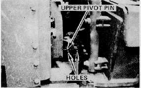
If required, adjust screw jack length for top pin
hole alignment. Install the upper pin and the four
(4) bolts.
NOTE
The holes in the sides of the pin cap must face
the sides of the machine for mounting the
pump drive shaft guard, and the grease fitting
must face the right side.
14.
Turn the battery disconnect switch "OFF."
Remove the engine drive yoke guard from the
fire wall and store in the tool box.
15.
Remove the pump drive shaft lock pin from the
yoke. Store the pin in the front tool box.
Manually rotate the pump, and install the pump
drive shaft with the grease fitting end toward the
engine. Tighten bolts securely.
16.
Install the pump driveshaft guards. Disconnect
the two hydraulic jumper hoses and the electrical
jumper cable and store them in the tool box.
17.
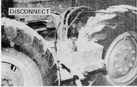
Disconnect lines and cables of the remote
control box from the machine. Install dust plugs
on all connections.
18.
Attach the remote control box cover, remove the
control box from the rear frame and install it on
the top of the front frame. Secure the control
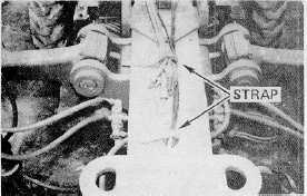
box with the two (2) bolts; strap the hoses and
cables to the front frame.
110

