TM 5-3805-263-14&P-1
26.
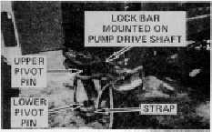
Install the upper pivot pin in the front frame,
insert the bolts and tighten to hold the pin. Install
the lower pivot pin in the rear frame and tighten
the retainer bolts. Install the bottom cap and
tighten to hold pin. Strap the top bushing to the
lower pivot on the front frame.
27.
Install the solid tandem links on each side of the
back of the frame using the jacks as necessary
to engage tandem links. Remove jacks and
store in tool box.
NOTE
At this point, the rear frame can be driven to
any convenient air lift slinging location. After
movement, but before slinging, proceed with
the following steps.
28.
Disconnect the remote control hoses and one
electrical cable from the engine lift frame rail.
Install dust plugs on all connections. Disconnect
the three (3) push/pull cables and install the dust
covers.
29.
Attach the remote control box cover. Remove
the control box from the rear frame and install it
on the top of the front frame. Secure the control
box with the two (2) bolts. Strap the hoses and
cables to the front frame.
30.
Store the articulation cylinder pins, caps, pump
drive shaft, drive shaft guard, jacks, tools,
jumpers and all other loose parts in the tool box
in the front frame. Secure tool box lid. Refer to
the tool box inventory list on page 2 to be sure
that all loose parts are accounted for.
NOTE
Cover the pivot pins and pivot pin bores with
plastic or other materiel to prevent foreign
matter from accumulating on the machined
surfaces. Secure the covering with tape.
31.
Disassembly is complete, the two sections are
now ready to be sling loaded.
106