TM 5-3805-263-14&P-1
5.
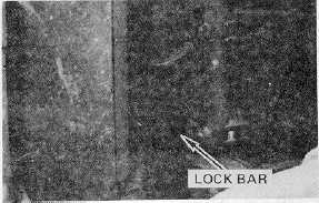
Install the pump drive shaft lock bar on the pump
coupling as shown using the drive shaft bolts.
Be sure that the free end of the lock bar is
pointing toward the right hand side of the
machine. Once the engine is started, this lock
bar will act as a pump rotation lock to prevent
hydraulic motoring.
6.
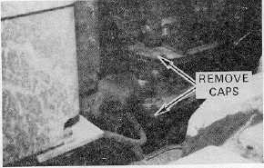
Remove the retainer caps from the top and
bottom of each articulation cylinder pin.
CAUTION
Be careful to avoid damaging fibre bushings in
cylinder rod ends.
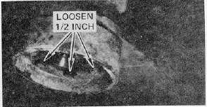
7. Remove the three (3) bolts and cap from the bottom
of the lower pivot pin.
8. Loosen the six (6) retainer bolts on the bottom of the
lower pin about 1/2 inch.
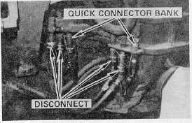
9. Disconnect the auxiliary hydraulic pump lines and air
lines at the quick connector banks on each side of the
machine. Remove dirt from dust covers and install on all
line connectors.
CAUTION
Keep hydraulic and air connectors clean. Do not
allow dirt or other contamination to enter fittings.
101