TM 5-3805-263-14&P-1
The Type II machine is equipped with all special tools
and equipment needed for sectionalization. Stored in the
tool box is a cable extraction tool 5R7047, and various
equipment such as jacks, articulation links, jumper
hoses and cables, tiedown straps, drive shaft guard, etc.
A remote control box is stored on the frame just forward
of the operator’s console (see disassembly steps 21 and
22).
The following procedures cover sectionalization for
helicopter transportation. The ROPS must be removed
before sectionalization is started, see Volume II.
NOTE
References to the left side, right side, front and
rear are always from the operator’s viewpoint.
DISASSEMBLY
A minimum of two people is required to accomplish
these procedures. Disassembly must be accomplished
on a firm, level surface. One person working on each
side of the machine will expedite disassembly.
NOTE
Whenever possible, return hardware, clamps,
etc. to the holes from which they were
removed. Be sure to tighten them enough so
that they will not loosen from vibration.
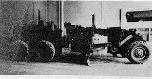
1.
Start the engine and center the blade tip and
side shift cylinders. Position the blade at 900 to
the frame and lower the blade to the ground.
Apply a small amount of blade down pressure to
reduce front weight on the articulation joint. Stop
the engine.
2.
Remove the two pump drive shaft guard halves.
3.
Remove the pump drive shaft.
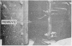
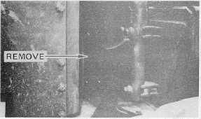
4.
Remove the four (4) outer bolts from the top of
the upper pivot pin.
100