TM 5-3805-263-14&P-1
7.
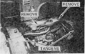
Remove the straps securing the articulation
cylinders to the frame and the hoses to the
tandems. Pull the cylinders away from the
frame. Store the straps in the tool box. Remove
the upper pivot pin from the front frame and
lower pivot pin from the rear frame.
8.
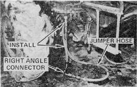
Install the jumper hoses for the auxiliary pump,
one supply and one return. The hose from the
engine with a right angle connector connects to
the right side of the front frame via the jumper.
Use the identification tags to connect the cables.
Install the wiring harness jumper between the
engine fire wall of the rear frame and the lower
platform of the front frame.
9.
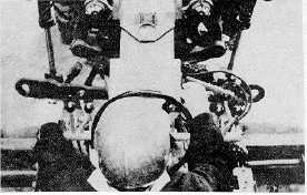
Start the engine and move the unit very slowly
toward the front frame. DO NOT STEER.
Position the front frame relative to the rear frame
with the blade control levers. While the engine
part approaches, hold the appropriate blade
lever in the desired position and use the auxiliary
pump switch INTERMITTENTLY to align the top
pin joint.
10.
Shift the tranmission to neutral and STOP THE
ENGINE.
11.
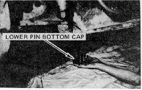
If required, adjust jack lengths and use the blade
control levers with auxiliary pump switch to align
the bottom pin hole. Grease the pivot pins and
pivot pin bores and then carefully install the
lower pin.
12.
Install the retainer bolts on the top and bottom of
the lower pin and tighten them. Install the
bottom cap on the lower pin. Tighten all bolts
securely.
109