TM 5-3805-263-14&P-1
10.
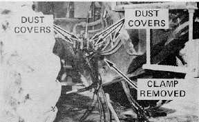
Remove the clamps from each side of the front
frame that secure the various lines and cables.
Disconnect the four (4) push/pull cables,
unscrew the shielding collar and install dust
covers on each cable end. Three (3) cables are
on the right hand side and one cable is on the
left hand side of the machine.
NOTE
When disconnecting the shaft of push/pull
cables, move the appropriate control lever in
the operator’s compartment as needed to aid in
disconnection.
11.
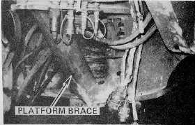
Relocate the three (3) push/pull cables and all
lines to the right side of the rear frame behind
the platform brace.
12.
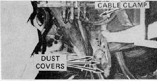
Disconnect
the
strap
holding
the
wiring
connectors to the bar near the underside of the
lower
pivot
pin.
Disconnect
the
wiring
connectors and install dust covers on all
connectors. Reinstall cable clamps.
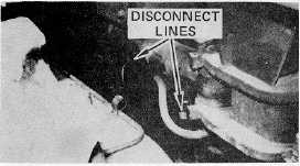
NOTE
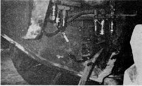
Slightly loosen the line fittings at the lock
valve(s)
to
allow
pressure
to
leak
out,
disconnect
the
lines
at
the
articulation
cylinder(s) and retighten the line fittings at the
lock valve(s).
WARNING
Use
adequate
eye
protection
when
disconnecting pressurized lines. Dust, fluid or
other foreign matter may be blown into eyes.
13.
Disconnect the articulation cylinder lines from
each side of the machine. Install dust covers on
all connectors.
102