TM 5-3805-261-34
FUEL SYSTEM MAINTENANCE. (cont)
3-28.
Governor. (Sheet 11 of 17)
ASSEMBLY (cont)
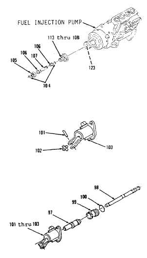
17.
Install items 113 thru 108 as an
assembly on shaft (123, Figure
3-128).
18.
Install ring (104) in lower
groove of shaft (123).
19.
Install spring (107), two sleeves
(106) and bearing (105) on shaft
(123).
20.
Using suitable spring compressor,
compress spring (107).
21.
Install ring (104) in upper
groove of shaft (123).
22.
Release spring (107) and remove
spring compressor.
23.
Install pin (101) on lever (102,
Figure 3-127). Stake pin in four
places 90 degrees apart on each
side of fork of cylinder (103).
Lever must turn freely after
assembly.
24.
Install new preformed packing
(100) on sleeve (99, Figure
3-126).
25.
Using clean grease, lubricate
sleeve (99), piston (98) and
valve (97) and install in items
103 thru 101 as an assembly.
26.
Install ring (96) in groove in
center of items 103 thru 97
(Figure 3-125).
27.
Install sleeve (95), spring (94),
seat (93) and ring (92). Engage
sleeve (95) with lever (102).
Go to Sheet 12
Figure 3-126.
Figure 3-127.
Figure 3-128.
3-154