TM 5-3805-261-34
FUEL SYSTEM MAINTENANCE.
3-28.
Governor. (Sheet 10 of 17)
ASSEMBLY
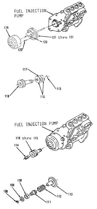
6.
Position items 127 thru 121
(Figure 3-132) as an assembly on
rear of fuel injection pump.
7.
Install four bolts (120).
8
Using a wood block the same
circumference as the new shield
(119), with a hole in the middle
for shaft (123) and a soft hammer
to drive new shield (119) into
position, install new shield
(119). Stake bottom of new
shield (119) in two places 180
degrees apart.
9.
Using clean oil, lubricate riser
(118).
10.
Install riser bearing (117), two
races (116) and ring (115) on
riser (118, Figure 3-131).
11.
Install items 118 thru 115 as an
assembly (Figure 3-130) in fuel
injection pump.
12.
Using clean oil, lubricate spring
(114) and install.
13.
Install spring (112) on seat
(113, Figure 3-129).
14.
Install seat (111) in spring
(112).
15.
Position spool (110) and ring
(109) on seat (111).
16.
Install ring (108) in seat (111).
Go to Sheet 11
Figure 3-129.
Figure 3-130.
Figure 3-131.
Figure 3-132.
3-153