TM 5-3805-261-34
FUEL SYSTEM MAINTENANCE.
3-28.
Governor. (Sheet 16 of 17)
INSTALLATION
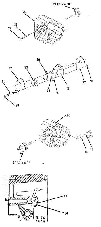
39.
Position items 33 thru 30 as an
assembly on inside of housing
(65, Figure 3-114).
40.
Install ring (28) in groove of
shaft (29).
41.
Install items 29 and 28 as an
assembly through housing (65)
into lever (33).
42.
Position spring (26) in groove of
cam on shaft (27, Figure 3-113).
43.
Install pin (25) so tip of pin
(25) engages in hole at end of
spring (26) when installed in
shaft (27).
44.
Install dowel (24) to hold pin
(25) in shaft (27).
45.
Position stop (23) and two plates
(22) on shaft (27).
46.
Install two pins (21) and four
‘
rings (20).
47.
Position shaft items 27 thru 20
as an assembly through housing
(65, Figure 3-112).
48.
Install levers (15 and 14) on
shaft (27).
49.
Install items 27 thru 20 as an
assembly.
50.
Turn shaft (27) counterclockwise
toward rear of housing (65).
51.
Adjust setscrew (30, Figure
3-139) if removed.
52.
Tighten nut (31) to 15 lb-in
torque.
Go to Sheet 17
Figure 3-114.
Figure 3-113.
Figure 3-112.
Figure 3-139.
3-159