
TM 5-3805-293-23-5
0326
INSTALLATION
000326
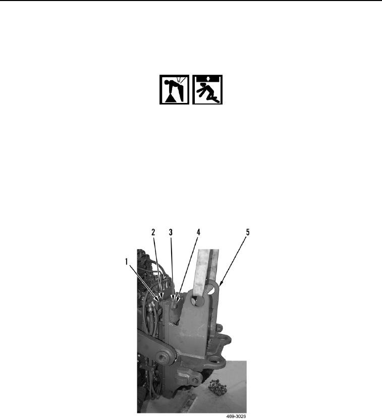
1. Attach sling and lifting device to tiedown assembly (Figure 3, Item 5).
2. Install two bolts (Figure 3, Item 4), spacers (Figure 3, Item 3), spacers (Figure 3, Item 2) and nuts (Figure 3,
Item 1) on tiedown assembly (Figure 3, Item 5). Hand tighten only.
WARN I N G
Use extreme caution when handling heavy parts. Provide adequate support and use
assistance during procedure. Ensure that any lifting device used is in good condition and
of suitable load capacity. Keep clear of heavy parts supported only by lifting device.
Failure to follow this warning may result in injury or death to personnel.
N OT E
Tiedown assembly weig s 482 lb (219 kg).
h
Upper right and left bolt holes on front frame are slotted to allow tiedown assembly
mounting bolts to slide in when tiedown assembly is installed on machine.
3. Using lifting device, install tiedown assembly (Figure 3, Item 5), and two bolts (Figure 3, Item 4) and nuts
(Figure 3, Item 1) on machine.
Figure 3. Tiedown Assembly.
0326