
TM 5-3805-293-23-5
0326
INSTALLATION CONTINUED
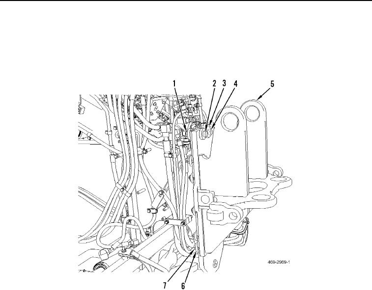
4. Install 12 bolts (Figure 4, Item 4), spacers (Figure 4, Item 3), spacers (Figure 4, Item 6), and nuts (Figure 4,
Item 7), on tiedown assembly (Figure 4, Item 5). Torque to 275 37 lb-ft (373 50 Nm).
5. Torque two bolts (Figure 4, Item 2) and nuts (Figure 4, Item 1) to 275 37 lb-ft (373 50 Nm).
6. Remove sling and lifting device from tiedown assembly (Figure 4, Item 5).
Figure 4. Tiedown Assembly.
0326