
TM 5-3805-293-23-5
0326
INSTALLATION CONTINUED
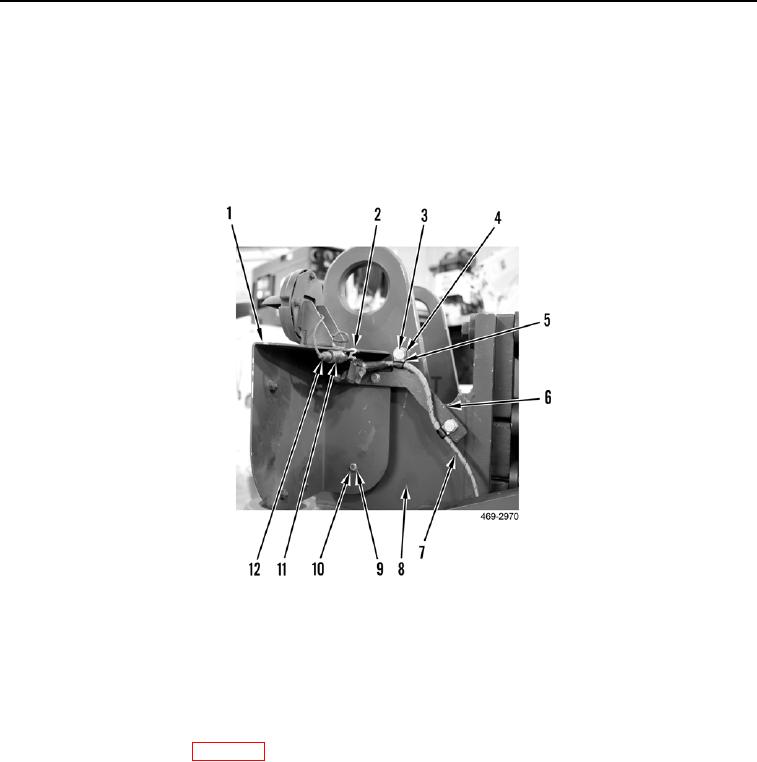
7. Install bracket (Figure 5, Item 1), bracket (Figure 5, Item 6), three washers (Figure 5, Item 9), and bolts (Figure
5, Item 10) on tiedown assembly (Figure 5, Item 8).
8. Position wiring harness (Figure 5, Item 7) and install two clips (Figure 5, Item 5), washers (Figure 5, Item 4),
and bolts (Figure 5, Item 3) on bracket (Figure 5, Item 6).
9. Install new tiedown strap (Figure 5, Item 2) on bracket (Figure 5, Item 1).
10. Connect blackout light connector (Figure 5, Item 12) to wiring harness connector (Figure 5, Item 11).
Figure 5. Blackout Light Bracket.
0326
END OF TASK
FOLLOW-ON TASKS
000326
1. Install nose cover (WP 0224).
2. Replace scarifier teeth in storage bracket (TM 5-3805-293-10).
3. Install scarifier assembly (WP 0325).
END OF TASK
END OF WORK PACKAGE