
TM 5-3805-293-23-5
0321
CLEANING AND INSPECTION
000321
Clean and inspect all parts IAW Mechanical General Maintenance Instructions (WP 0346).
END OF TASK
INSTALLATION
000321
1. Start machine and lower drawbar onto circle assembly (TM 5-3805-293-10).
2. Position machine to engage circle drive pinion on circle assembly.
3. Shut off machine (TM 5-3805-293-10).
4. Install circle guide shoes (WP 0304).
5. Install drawbar wearstrips (WP 0303).
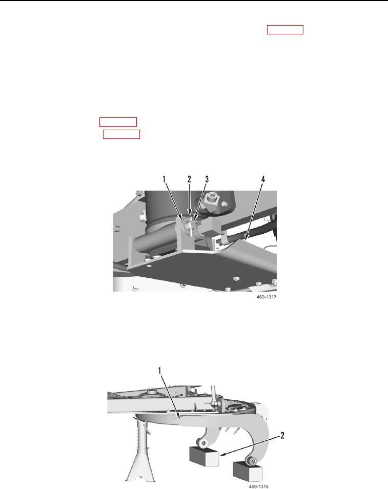
6. Install bracket (Figure 6, Item 4), pin (Figure 6, Item 3), washer (Figure 6, Item 1), and new cotter pin (Figure 6,
Item 2) on machine.
Figure 6. Bracket.
0321
7. Start machine (TM 5-3805-293-10).
8. Raise circle assembly (Figure 7, Item 1) and remove wood blocks (Figure 7, Item 2) from circle assembly.
Figure 7. Circle Assembly.
0321