
TM 5-3805-293-23-5
0321
INSTALLATION CONTINUED
9. Position machine on blade assembly (TM 5-3805-293-10).
10. Shut off machine (TM 5-3805-293-10).
N OT E
Shaft assembly procedure is identical for left and right sides. Right side is shown.
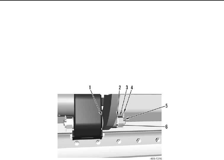
11. Install shims (Figure 8, Item 1) and shaft assembly (Figure 8, Item 5) on circle assembly (Figure 8, Item 6).
12. Install two washers (Figure 8, Item 2) and nuts (Figure 8, Item 3) on shaft assembly. Tighten nut until flush with
circle assembly; back nut off one slot.
13. Install new cotter pin (Figure 8, Item 4) on circle assembly (Figure 8, Item 6).
Figure 8. Blade Shaft Assembly.
0321