
TM 5-3805-293-23-5
0321
REMOVAL CONTINUED
12. Start machine (TM 5-3805-293-10) and position machine away from blade assembly.
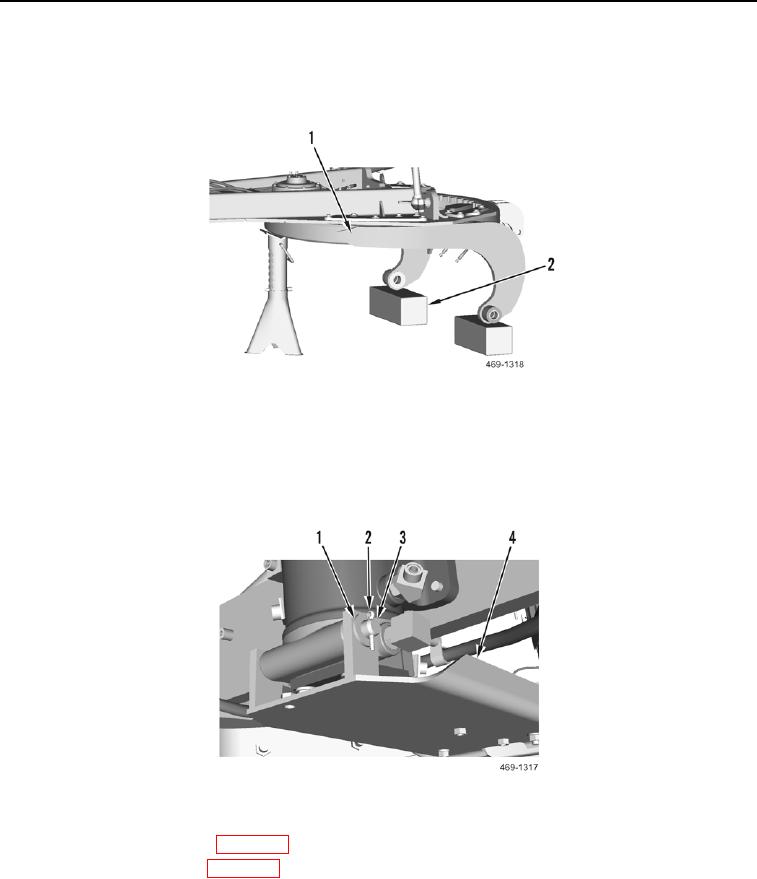
13. Lower circle assembly (Figure 4, Item 1) onto wood blocks (Figure 4, Item 2).
Figure 4. Circle Assembly.
0321
14. Shut off machine (TM 5-3805-293-10).
15. Remove cotter pin (Figure 5, Item 2), washer (Figure 5, Item 1), pin (Figure 5, Item 3), and bracket (Figure 5,
Item 4) from machine. Discard cotter pin.
Figure 5. Bracket.
0321
16. Remove drawbar wearstrips (WP 0303).
17. Remove circle guide shoes (WP 0304).
18. Start machine (TM 5-3805-293-10) and position circle drive pinion away from circle assembly.
19. Raise drawbar off of circle assembly.
20. Shut off machine (TM 5-3805-293-10).
END OF TASK