
TM 5-3805-293-23-5
0303
ADJUSTMENT
000303
N OT E
Make sure circle shoe wearstrips ae completely seated in circle shoes.
r
Circle shoe mounting fasteners must be tight.
After all the adjustments have been performed, blade circle must rotate freely without
binding.
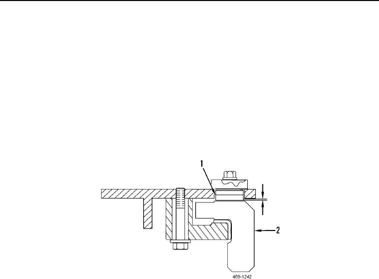
1. Measure clearance between the top of blade circle (Figure 6, Item 2) and the bottom of drawbar wearstrips
(Figure 6, Item 1). Maintain a maximum clearance of 0.02 in. (0.5 mm) (Figure 6).
2. Adjust number of shims to achieve proper clearance.
3. Repeat process for each circle shoe.
4. Rotate circle and inspect for binding (TM 5-3805-293-10).
Figure 6. Wearstrip Measurement.
0303
END OF TASK
END OF WORK PACKAGE