TM 5-3805-293-23-5
0303
REMOVAL
000303
N OT E
Remove debris and abrasive material from the entire blade circle for accurate adjustment.
1. Rotate blade at an angle of 90 degrees to frame (TM 5-3805-293-10).
2. Lift blade 0.39 in. (10 mm) off the ground (TM 5-3805-293-10).
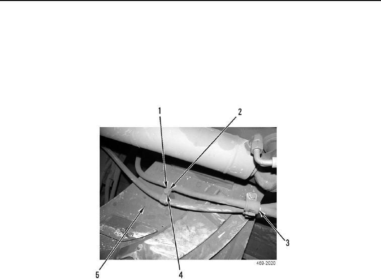
3. Remove two bolts (Figure 1, Item 1), washers (Figure 1, Item 4), two hydraulic hose clamps (Figure 1,
Item 2), and two hydraulic hose clamps (Figure 1, Item 3) from drawbar (Figure 1, Item 5).
Figure 1. Hydraulic Hose Clamps.
0303
N OT E
Note location of wearstrip and the number of shims removed to aid in installation.
4. Remove 12 bolts (Figure 2, Item 2), washers (Figure 2, Item 1), four plates (Figure 2, Item 3), and two plates
(Figure 2, Item 12) from drawbar (Figure 2, Item 11).
N OT E
The following task steps will properly seat the blade circle on the circle shoes for
adjustment.
5. Install bolt (Figure 2, Item 2) on drawbar (Figure 2, Item 11) at hole (Figure 2, Item 5). Tighten bolts to firmly
seat circle against shoes.
6. Install bolt (Figure 2, Item 2) on drawbar (Figure 2, Item 11) at hole (Figure 2, Item 8). Tighten bolts to firmly
seat circle against shoes.
7. Remove two pusher bolts (Figure 2, Item 6) and spacers (Figure 2, Item 7) from drawbar (Figure 2, Item 11).
8. Install two pusher bolts (Figure 2, Item 6) without spacers (Figure 2, Item 7) on drawbar (Figure 2,
Item 11). Tighten bolts to firmly seat circle against shoes.
9. Remove shims (Figure 2, Item 4), six spacer plates (Figure 2, Item 10), and wearstrips (Figure 2, Item 9) from
drawbar (Figure 2, Item 11).

