TM 5-3805-293-23-5
0304
ADJUSTMENT CONTINUED
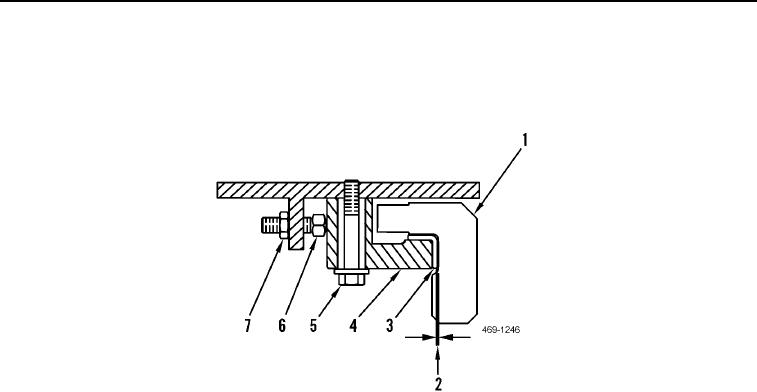
6. Loosen bolts (Figure 3, Item 5) and locknuts (Figure 3, Item 7).
7. Turn adjusting bolts (Figure 3, Item 6) inward or outward in order to attain a clearance within 1.95 to 2.07 in.
(49.5 to 52.5 mm).
Figure 3. Circle Guide Shoe Adjustment.
0304
N OT E
If the circle shoes are moved outward, it may be necessary to slowly inch the machine in a
forward direction in order to place a light load between the circle guide shoe wearstrips
and the blade circle.
After adjustments have been made to any circle guide shoe, check the circle guide shoes
for proper clearance.
If you cannot attain the correct clearance measurement due to worn front circle guide shoe
wearstrips, replace the worn circle guide shoe wearstrips.
The adjusting bolts must be tight against he circle guide shoes before you tighten the
t
mounting fasteners and the locknuts.
After all the adjustments have been performed,the blade circle must rotate freely without
binding.
8. Tighten bolts (Figure 3, Item 5) and locknuts (Figure 3, Item 7).
9. Set all circle guide shoes (Figure 3, Item 4) to contact blade circle (Figure 3, Item 1).
10. Measure distance between each circle guide shoe wearstrip (Figure 3, Item 7) and blade circle (Figure 3,
Item 1). Clearance should be a maximum of 0.03 in. (0.8 mm) (Figure 3, Item 2).
11. Tighten bolts (Figure 3, Item 5) to a torque of 390 50 lb-ft (530 70 Nm).
12. Tighten locknuts (Figure 3, Item 7) to a torque of 150 22 lb-ft (200 30 Nm).
END OF TASK
END OF WORK PACKAGE

