
TM 5-3805-293-23-5
0304
ADJUSTMENT
000304
N OT E
Remove debris and abrasive material from the entire blade circle for accurate adjustment.
The engagement of circle pinion and the circleteeth is affected by the adjustment of circle
shoes.
1. Rotate blade at an angle of 90 degrees to frame.
2. Lower blade to the ground.
3. Inch machine forward to hold a light load on front circle guide shoe wearstrips.
4. Park machine.
N OT E
Adjust the front circle guide shoes one at a time.
Adjust the clearance equally for each front circle shoe.
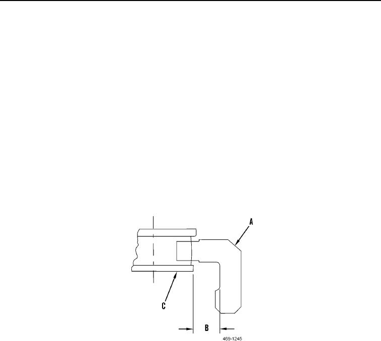
5. Measure clearance (Figure 2, Item B) between circle pinion bottom flange (Figure 2, Item C) and blade circle
inner machined surface (Figure 2, Item A). If clearance is not within 1.95 to 2.07 in. (49.5 to 52.5 mm), then
adjust clearance.
Figure 2. Circle Pinion Measurement.
0304