TM 5-3805-293-23-5
0294
INSTALLATION CONTINUED
000294
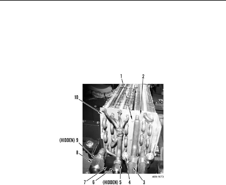
5. Install evaporator core (Figure 25, Item 10) in housing (Figure 25, Item 7).
6. Position A/C tube (Figure 25, Item 8) in cab. Install new O-ring (Figure 25, Item 9) and connect A/C tube to
evaporator core (Figure 25, Item 10).
7. Position A/C hose (Figure 25, Item 6) in cab. Install new O-ring (Figure 25, Item 5) and connect A/C hose to
evaporator core (Figure 25, Item 10).
8. Install heater core (Figure 25, Item 2) and four bolts (Figure 25, Item 1) in housing (Figure 25, Item 7).
9. Connect two coolant hoses (Figure 25, Item 3) to heater core (Figure 25, Item 2) and install two clamps (Figure
25, Item 4).
Figure 25. Heater Core Hoses and Bolts.
0294

