TM 5-3805-293-23-5
0294
DISASSEMBLY
000294
N OT E
Note orientation of actuator prior to removal to aid in installation.
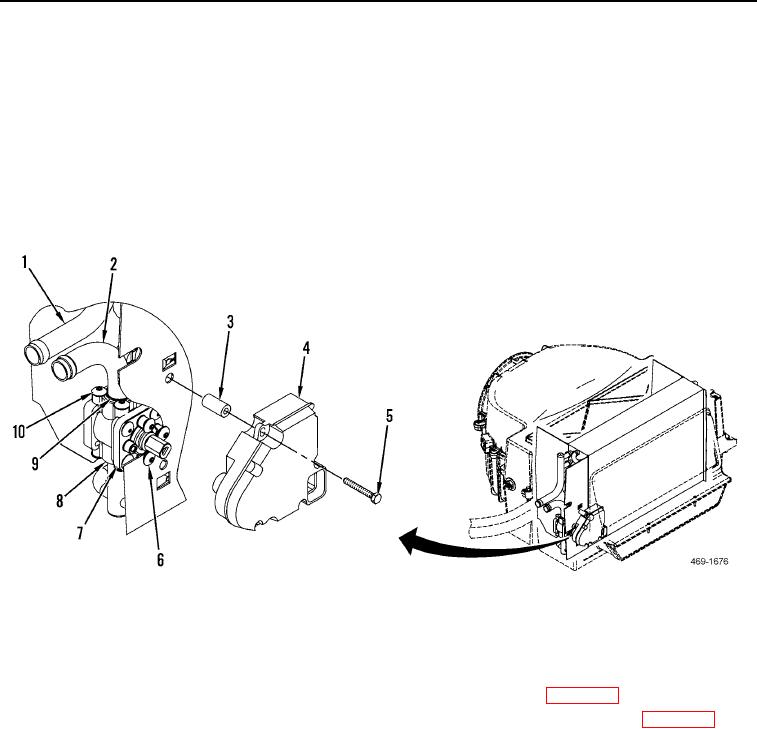
1. Remove two screws (Figure 21, Item 5), actuator (Figure 21, Item 4), and spacers (Figure 21, Item 3) from
heater core (Figure 21, Item 1).
2. Remove four screws (Figure 21, Item 6) from heater core (Figure 21, Item 1).
3. Remove eight screws (Figure 21, Item 10), tube (Figure 21, Item 2), O-ring (Figure 21, Item 9), coolant shut-off
valve (Figure 21, Item 7), and O-ring (Figure 21, Item 8) from heater core (Figure 21, Item 1). Discard O-rings.
Figure 21. Actuator and Coolant Shut-off Valve.
0294
END OF TASK
CLEANING AND INSPECTION
000294
1. Clean and inspect all parts IAW Mechanical General Maintenance Instructions (WP 0346).
2. Clean and inspect all electrical components IAW Electrical General Maintenance Instructions (WP 0347).
END OF TASK

