
TM 5-3805-293-23-5
0294
INSTALLATION CONTINUED
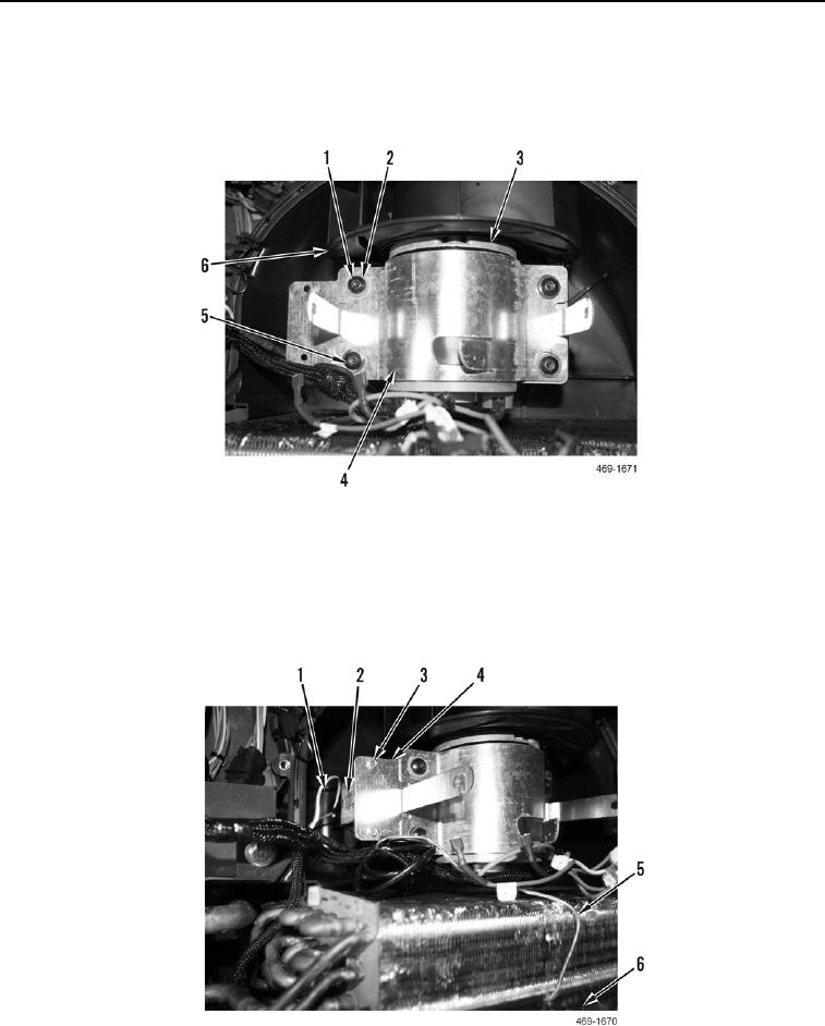
15. Install blower motor (Figure 29, Item 3) in housing (Figure 29, Item 6).
16. Install plate (Figure 29, Item 4), clamp (Figure 29, Item 5), four washers (Figure 29, Item 2), and screws
(Figure 29, Item 1) on blower motor (Figure 29, Item 3).
Figure 29. Blower Motor.
0294
17. Connect two wires (Figure 30, Item 1) to evaporator temperature switch (Figure 30, Item 2).
18. Install evaporator temperature switch (Figure 30, Item 2) and two bolts (Figure 30, Item 3) on blower motor
plate (Figure 30, Item 4).
19. Install evaporator temperature switch sensing bulb (Figure 30, Item 5) in evaporator core (Figure 30, Item 6).
Figure 30. Seal and Evaporator Temperature Switch.
0294