
TM 5-3805-293-23-4
0246
ASSEMBLY CONTINUED
000246
N OT E
The procedure for control valve assembly is identical for all control valves in the rear valve
bank. Repeat procedure for each control valve.
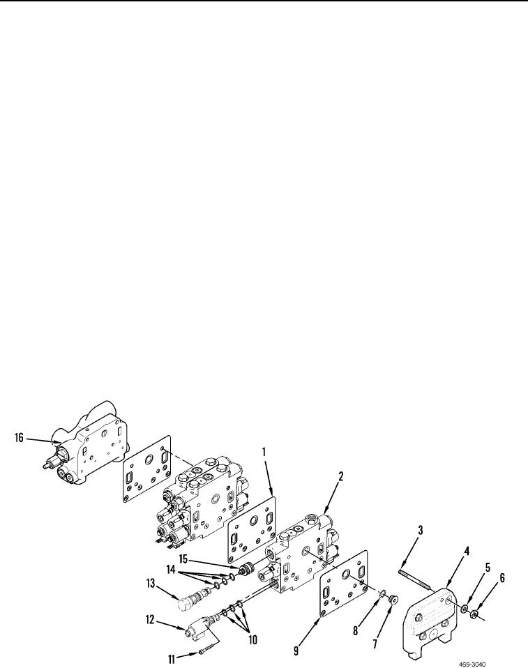
5. Install four studs (Figure 10, Item 3) on end cap (Figure 10, Item 16).
6. Install three new seals (Figure 10, Item 1) and two valves (Figure 10, Item 2) on studs (Figure 10, Item 3).
7. Install new O-ring (Figure 10, Item 8), plug (Figure 10, Item 7), valve (Figure 10, Item 2), and new seal
(Figure 10, Item 9) on studs (Figure 10, Item 3).
N OT E
Lifting link bracket attaches to upper right stud. Do not install washer and nut on stud at
this time.
8. Install end cap (Figure 10, Item 4), three washers (Figure 10, Item 5), and nuts (Figure 10, Item 6) on studs
(Figure 10, Item 3). Torque nuts to 41 7 lb-ft (55 9 Nm).
9. Install three new O-rings (Figure 10, Item 10), solenoid (Figure 10, Item 12), and bolt (Figure 10, Item 11) from
control valve (Figure 10, Item 2). Torque bolt to 9 lb-ft (12 Nm).
C AU T I O N
Do not adjust check valve; check valve is preset from factory. Adjusting check valve may
result in damage to equipment.
10. Install piston (Figure 10, Item 15), three new O-rings (Figure 10, Item 14), and check valve (Figure 10, Item 13)
on control valve (Figure 10, Item 2).
Figure 10. Valve Bank Fittings.
0246

