
TM 5-3805-293-23-4
0246
INSTALLATION CONTINUED
N OT E
Install wires as tagged during removal.
The procedure for valve bank connections is identical for left and right sides. Left-side
connections are shown in this procedure.
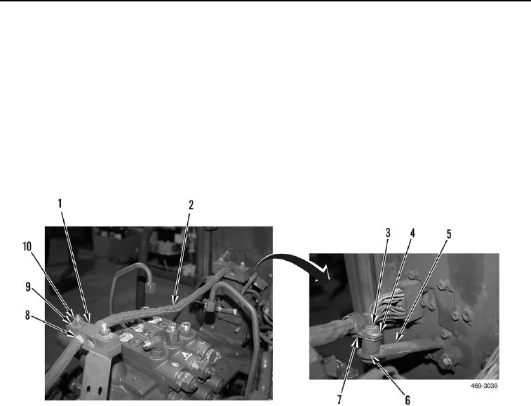
10. Reposition wiring harness (Figure 13, Item 2) on machine.
11. Install two spacers (Figure 13, Item 8), plates (Figure 13, Item 1), four washers (Figure 13, Item 9), and
locknuts (Figure 13, Item 10) on wiring harness (Figure 13, Item 2).
12. Install spacer (Figure 13, Item 6), clamp (Figure 13, Item 7), washer (Figure 13, Item 4), and bolt (Figure 13,
Item 3) on bracket (Figure 13, Item 5).
Figure 13. Wiring Harness.
0246

