
TM 5-3805-293-23-4
0246
DISASSEMBLY CONTINUED
N OT E
The procedure for control valve disassembly is identical for all control valves in the rear
valve bank. Repeat procedure for each control valve.
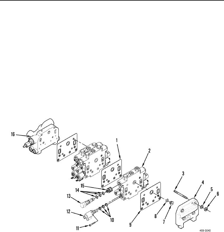
4. Remove check valve (Figure 8, Item 13), three O-rings (Figure 8, Item 14) and piston (Figure 8, Item 15) from
control valve (Figure 8, Item 2). Discard O-rings.
5. Remove bolt (Figure 8, Item 11), solenoid (Figure 8, Item 12), and three O-rings (Figure 8, Item 10) from
control valve (Figure 8, Item 2). Discard O-rings.
6. Remove three nuts (Figure 8, Item 6), washers (Figure 8, Item 5), and end cap (Figure 8, Item 4) from studs
(Figure 8, Item 3).
7. Remove seal (Figure 8, Item 9), valve (Figure 8, Item 2), plug (Figure 8, Item 7), O-ring (Figure 8, Item 8) from
studs (Figure 8, Item 3). Discard O-ring and gasket.
8. Remove three seals (Figure 8, Item 1) and two valves (Figure 8, Item 2) from studs (Figure 8, Item 3). Discard
gaskets.
9. Remove four studs (Figure 8, Item 3) from end cap (Figure 8, Item 16).
Figure 8. Valve Bank Fittings.
0246

