
TM 5-3805-293-23-4
0246
INSTALLATION CONTINUED
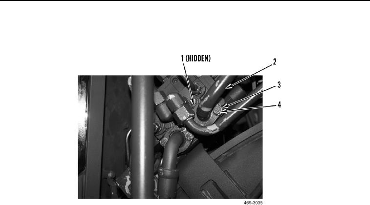
14. Install new O-ring (Figure 15, Item 1), line (Figure 15, Item 2), four washers (Figure 15, Item 3), and bolts
(Figure 15, Item 4) on machine.
Figure 15. Right-Side Line.
0246
N OT E
Install harness connectors as tagged during removal.
15. Connect six harness connectors (Figure 16, Item 14) on rear valve bank (Figure 16, Item 1).
N OT E
Install lines as tagged during removal.
16. Install new O-ring (Figure 16, Item 6) and pump pressure inlet line (Figure 16, Item 7) on rear valve bank
(Figure 16, Item 1).
17. Install new O-ring (Figure 16, Item 10) and pilot/load sense line (Figure 16, Item 11) on rear valve bank
(Figure 16, Item 1).
18. Install new O-ring (Figure 16, Item 9) and pilot/shutoff sense line (to front valve) (Figure 16, Item 8) on rear
valve bank (Figure 16, Item 1).
19. Install new O-ring (Figure 16, Item 18) and pilot/shutoff pressure inlet line (Figure 16, Item 17) on rear valve
bank (Figure 16, Item 1).
20. Install new O-ring (Figure 16, Item 15) and left return line (Figure 16, Item 16) on rear valve bank (Figure 16,
Item 1).
21. Install new O-ring (Figure 16, Item 12) and right return line (Figure 16, Item 13) on rear valve bank (Figure 16,
Item 1).
22. Install new O-ring (Figure 16, Item 19) and pilot/shutoff pressure outlet line (Figure 16, Item 20) on rear valve
bank (Figure 16, Item 1).
23. Install new O-ring (Figure 16, Item 21) and pump pressure output line (Figure 16, Item 22) on rear valve bank
(Figure 16, Item 1).

