
TM 5-3805-293-23-4
0245
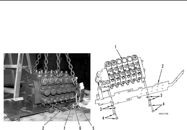
REMOVAL CONTINUED
43. Remove sling and lifting device from front valve bank mounting plate (Figure 10, Item 2).
44. Remove two bolts (Figure 10, Item 7), washers (Figure 10, Item 6), and link brackets (Figure 10, Item 5) from
front valve bank mounting plate (Figure 10, Item 2).
45. Remove four bolts (Figure 10, Item 4), washers (Figure 10, Item 3), and front valve bank (Figure 10, Item 1)
from mounting plate (Figure 10, Item 2).
Figure 10. Front Valve Bank Mounting Plate.
0245
END OF TASK
DISASSEMBLY
000245
N OT E
The procedure for control valve disassembly isidentical for all control valves in the front
valve bank. Repeat procedure for each control valve.
The procedure for control valve disassembly isidentical for left and right sides. Left control
valve disassembly is shown in this procedure.
1. Remove 12 hydraulic fittings (Figure 11, Item 1) and O-rings (Figure 11, Item 2) from front valve bank
(Figure 11, Item 3). Discard O-rings.
N OT E
The procedure for check valve and solenoid disassembly is the same for all valves.
2. Remove check valve (Figure 11, Item 17), three O-ring seals (Figure 11, Item 16) and piston (Figure 11,
Item 18) from front valve bank (Figure 11, Item 3). Discard O-rings.
Change 1

