
TM 5-3805-293-23-4
0245
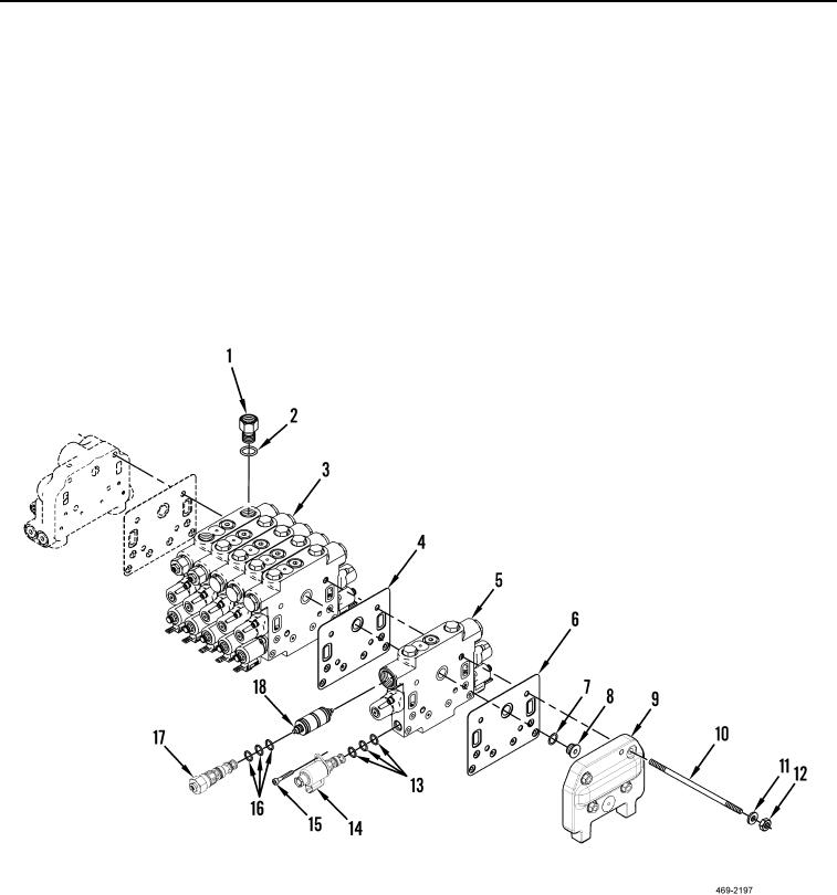
DISASSEMBLY CONTINUED
000245
3. Remove bolt (Figure 11, Item 15), solenoid (Figure 11, Item 14), and three O-rings (Figure 11, Item 13) from
control valve (Figure 11, Item 5). Discard O-rings.
4. Remove four nuts (Figure 11, Item 12), washers (Figure 11, Item 11), studs (Figure 11, Item 10) and end cap
(Figure 11, Item 9) from front valve bank (Figure 11, Item 3).
5. Remove plug (Figure 11, Item 8), O-ring (Figure 11, Item 7), and gasket (Figure 11, Item 6) from valve
(Figure 11, Item 5). Discard O-ring and gasket.
N OT E
The disassembly procedure for each valve is the same.
6. Remove valve (Figure 11, Item 5) and gasket (Figure 11, Item 4) from front valve bank (Figure 11, Item 3).
Discard gasket.
Figure 11. Front Valve Bank.
0245
END OF TASK
CLEANING AND INSPECTION
000245
Clean and inspect all parts IAW Mechanical General Maintenance Instructions (WP 0346).
END OF TASK
Change 1

