TM 5-3805-293-23-3
0114
INSTALLATION CONTINUED
N OT E
Install wires as tagged during removal.
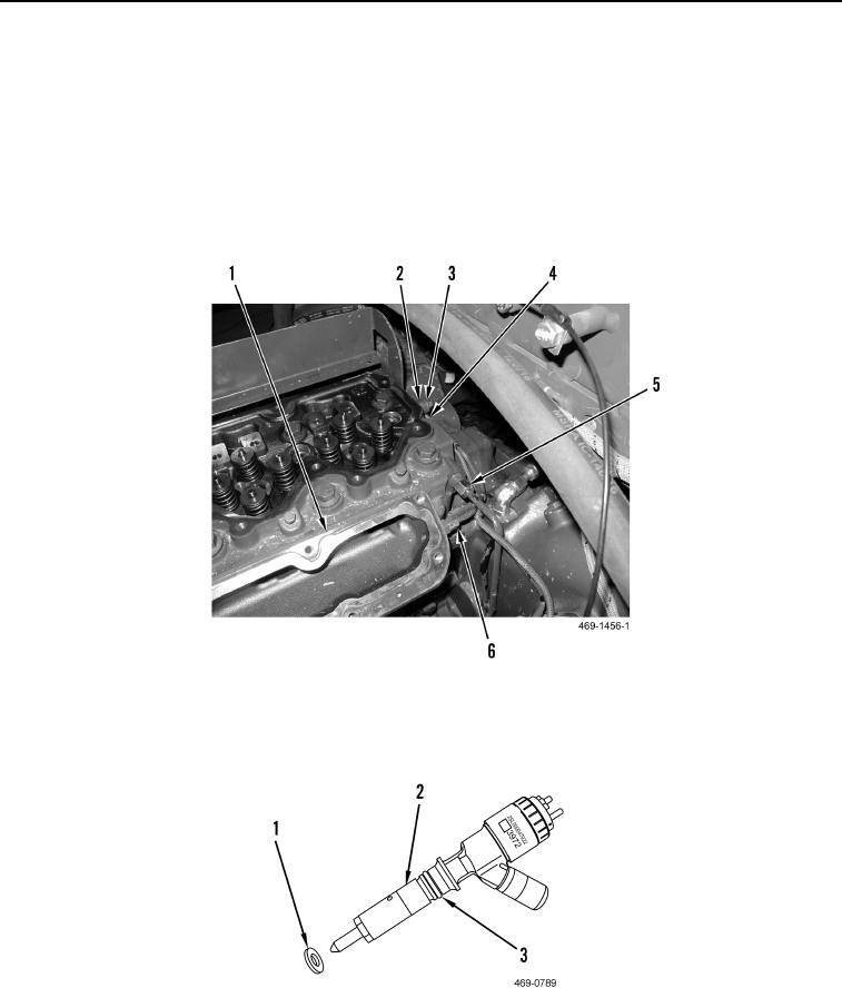
16. Install oil line (Figure 26, Item 5) on cylinder head (Figure 26, Item 1).
17. Install waste gate pressure tube (Figure 26, Item 6) on cylinder head (Figure 26, Item 1).
18. Install spacer (Figure 26, Item 2), clamp (Figure 26, Item 4), and bolt (Figure 26, Item 3) on cylinder head
(Figure 26, Item 1).
Figure 26. Oil and Waste Gate Pressure Lines.
0114
19. Install new O-ring (Figure 27, Item 3) and new sealing washer (Figure 27, Item 1) on fuel injector (Figure 27,
Item 2).
Figure 27. Fuel Injector Seals.
0114

