
TM 5-3805-293-23-3
0114
INSTALLATION CONTINUED
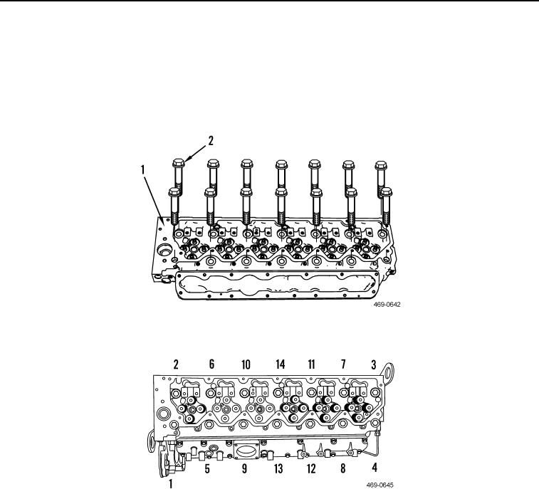
7. Lubricate 14 new cylinder head bolts (Figure 22, Item 2) with clean engine oil and install on cylinder head
(Figure 22, Item 1). Hand tighten only.
8. Torque cylinder head bolts (Figure 22, Item 2) in sequence shown (Figure 23) to 37 lb-ft (50 Nm).
9. Torque cylinder head bolts (Figure 22, Item 2) in sequence shown (Figure 23) to 74 lb-ft (100 Nm).
10. Torque cylinder head bolts (Figure 22, Item 2) in sequence shown (Figure 23) an additional 225 degrees.
Figure 22. Cylinder Head Bolts.
0114
Figure 23. Cylinder Head Bolt Tightening Sequence.
0114