
TM 5-3805-293-23-3
0114
INSTALLATION CONTINUED
WARN I N G
Use extreme caution when handling heavy parts. Provide adequate support and use
assistance during procedure. Ensure any lifting device used is in good condition and of
suitable load capacity. Keep clear of heavy parts supported only by lifting device. Failure
to follow this warning may result in injury or death to personnel.
N OT E
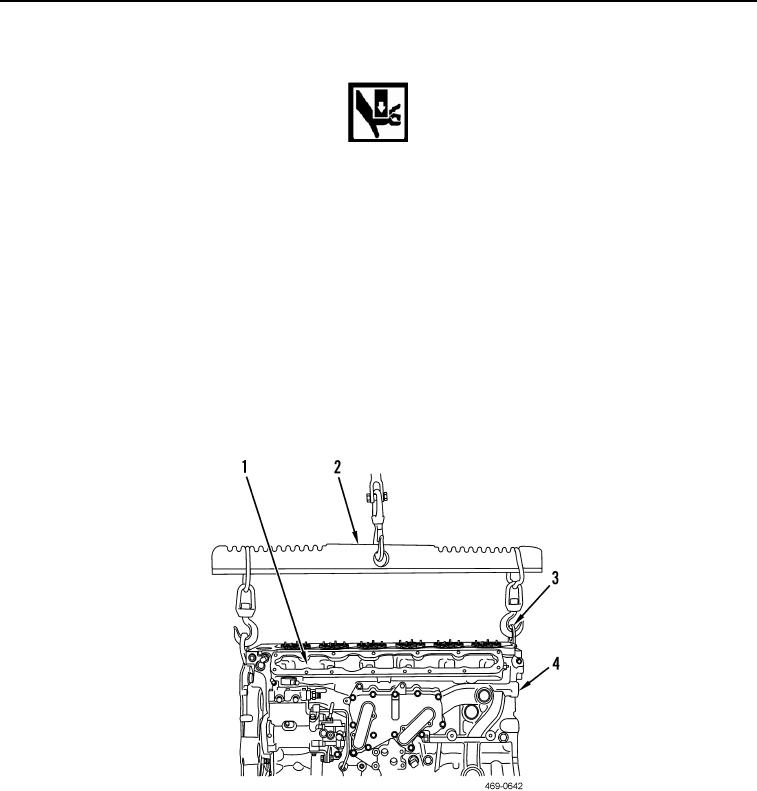
Cylinder head weighs approximately 165 lb (75 kg).
2. Attach link bracket (Figure 21, Item 3) to cylinder head (Figure 21, Item 1).
3. Attach lifting device (Figure 21, Item 2) to cylinder head (Figure 21, Item 1).
4. Use lifting device (Figure 21, Item 2) to install cylinder head (Figure 21, Item 1) onto cylinder block (Figure 21,
Item 4).
5. Remove lifting device (Figure 21, Item 2) from cylinder head (Figure 21, Item 1).
6. Remove link bracket (Figure 21, Item 3) from cylinder head (Figure 21, Item 1).
Figure 21. Cylinder Head Lifting Device.
0114