TM 5-3805-293-23-3
0114
ASSEMBLY CONTINUED
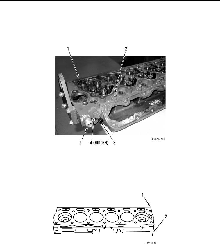
7. Install six glow plug hole plugs (Figure 19, Item 2) in cylinder head (Figure 19, Item 1).
8. Install new O-ring (Figure 19, Item 4) and coolant temperature sensor (Figure 19, Item 3) on cylinder head
(Figure 19, Item 1).
9. Install fitting (Figure 19, Item 5) on cylinder head (Figure 19, Item 1).
Figure 19. Coolant Control Valve.
0114
END OF TASK
INSTALLATION
000114
1. Align new cylinder head gasket (Figure 20, Item 1) on cylinder block (Figure 20, Item 2).
Figure 20. Cylinder Head Gasket.
0114

