
TM 5-3805-293-23-3
0114
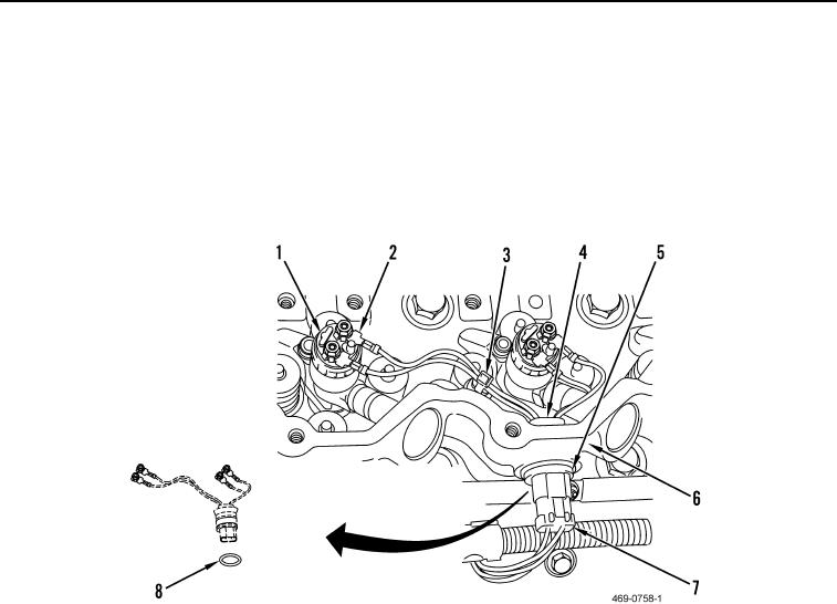
INSTALLATION CONTINUED
27. Lubricate three new O-rings (Figure 30, Item 8) with O-ring assembly compound. Install three fuel injector
harness connectors (Figure 30, Item 4) and O-rings on valve mechanism cover base (Figure 30, Item 6).
28. Install three snap rings (Figure 30, Item 5) on fuel injector harness connectors (Figure 30, Item 4) and connect
fuel wiring harness plugs (Figure 30, Item 7).
29. Install three clips (Figure 30, Item 3) on valve cover base (Figure 30, Item 6).
30. Install 12 fuel injector harness connections and nuts (Figure 30, Item 2) on six fuel injectors (Figure 30, Item 1).
Torque to 21 lb-in. (2.4 Nm).
Figure 30. Fuel Injector Harness.
0114