
TM 5-3805-293-23-2
0035
FUEL TRANSFER PUMP TEST CONTINUED
00035
Test Step 3. Test Voltage Supply Circuit.
00035
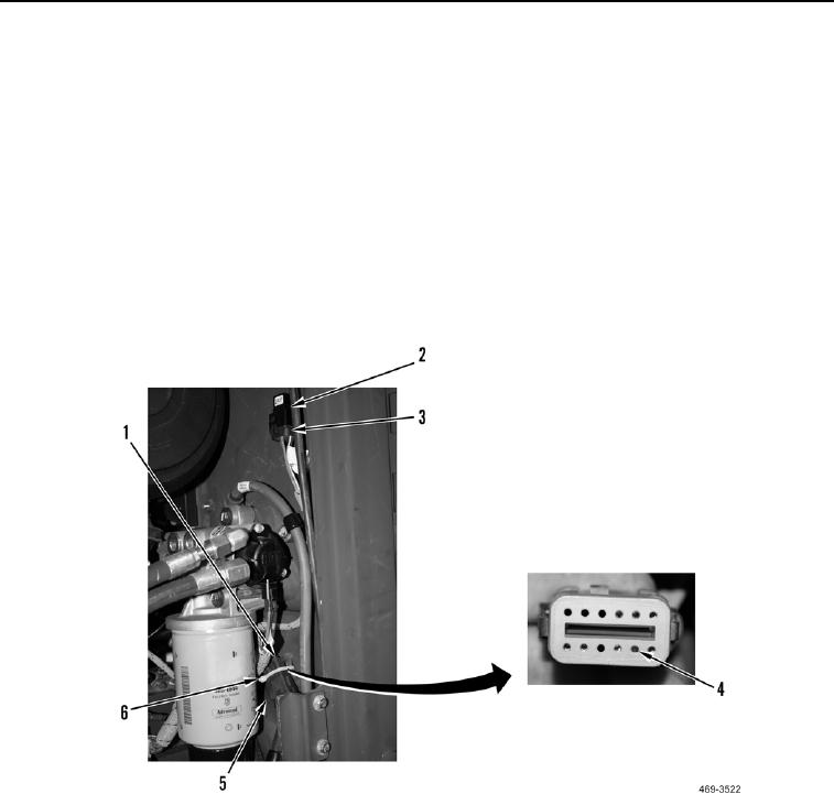
1. Connect harness connector FE-C4 (Figure 16, Item 3) to fuel prime pump relay (Figure 16, Item 2).
2. Turn the ignition switch to the OFF position.
3. Remove tiedown strap (Figure 16, Item 6). Discard tiedown strap.
4. Disconnect harness connector FA-C18 (Figure 16, Item 5) from harness connector FE-C1 (Figure 16, Item 1).
5. Turn battery disconnect switch to ON position.
6. Using a digital multimeter, measure voltage supply circuit 150-RD for voltage between harness connector FA-
C18 terminal 5 (Figure 16, Item 4) and ground. Voltage should be within 18 - 26 volts.
a. Voltage OK - Replace fuel wiring harness (WP 0064).
b. Voltage NOT OK - Replace rear wiring harness (WP 0188).
Figure 16. Fuel Prime Pump Relay and Inline Harness Connectors.
0035