
TM 5-3805-293-23-2
0035
FUEL TRANSFER PUMP TEST CONTINUED
00035
Test Step 2. Test Fuel Prime Pump Relay Switch Circuit and Fuel Prime Pump Control Circuit.
00035
1. Turn the ignition switch to the OFF position.
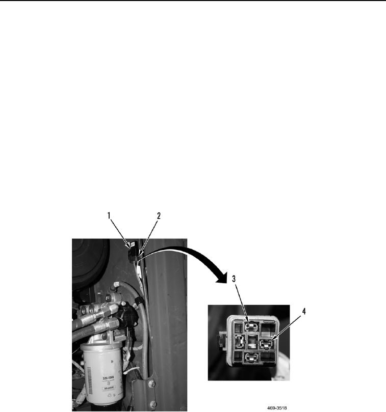
2. Disconnect harness connector FE-C4 (Figure 13, Item 2) from fuel prime pump relay (Figure 13, Item 1).
3. Turn the ignition switch to the ON position.
4. Using a digital multimeter, measure voltage supply circuit 150-RD for voltage between fuel prime pump relay
harness connector FE-C4 terminal 1 (Figure 13, Item 4) and ground. Voltage should be within 18 - 26 volts.
a. Voltage OK - Proceed to step 5.
b. Voltage NOT OK - Proceed to Test Step 3.
5. Using a digital multimeter, measure voltage supply circuit 150-RD between fuel prime pump relay harness
connector FE-C4 terminal 5 (Figure 13, Item 3) and ground. Voltage should be within 18-26 volts.
a. Voltage OK - Proceed to step 6.
b. Voltage NOT OK - Proceed to Test Step 3.
6. Turn the ignition switch to the OFF position.
7. Connect fuel prime pump relay harness connector FE-C4 (Figure 13, Item 2) to fuel prime pump relay (Figure
13, Item 1).
Figure 13. Fuel Pump Relay Harness Connector.
0035