
TM 5-3805-293-23-2
0032
FLYWHEEL, FLYWHEEL HOUSING AND GEAR GROUP INSPECT
Alignment of Flywheel Face
00032
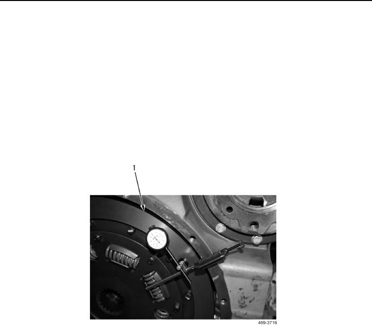
1. Mount dial indicator on face of flywheel housing.
2. Position dial indicator on face of flywheel (Figure 22, Item 1). Set pointer of dial indicator to 0 inch (0 mm).
3. Turn flywheel. Note reading on dial indicator every 45 degrees.
N OT E
During check, keep crankshaft pressed toward front of engine to remove any end
clearance.
4. Calculate difference between lowest measurement and highest measurement of four locations.
a. Difference must not be greater than 0.001 inch (0.03 mm) for every 1.0 inch (25 mm) of radius of flywheel.
b. Radius of flywheel is measured from axis of crankshaft to contact point of dial indicator.
Figure 22. Flywheel Face.
032
Change 1