TM 5-3805-293-23-2
0032
FLYWHEEL, FLYWHEEL HOUSING AND GEAR GROUP INSPECT CONTINUED
Flywheel Housing - Inspect Concentricity of Flywheel Housing
00032
N OT E
Check must be made with flywheel removed (refer to WP 0100). Install bolts for flywheel
housing and tighten lightly.
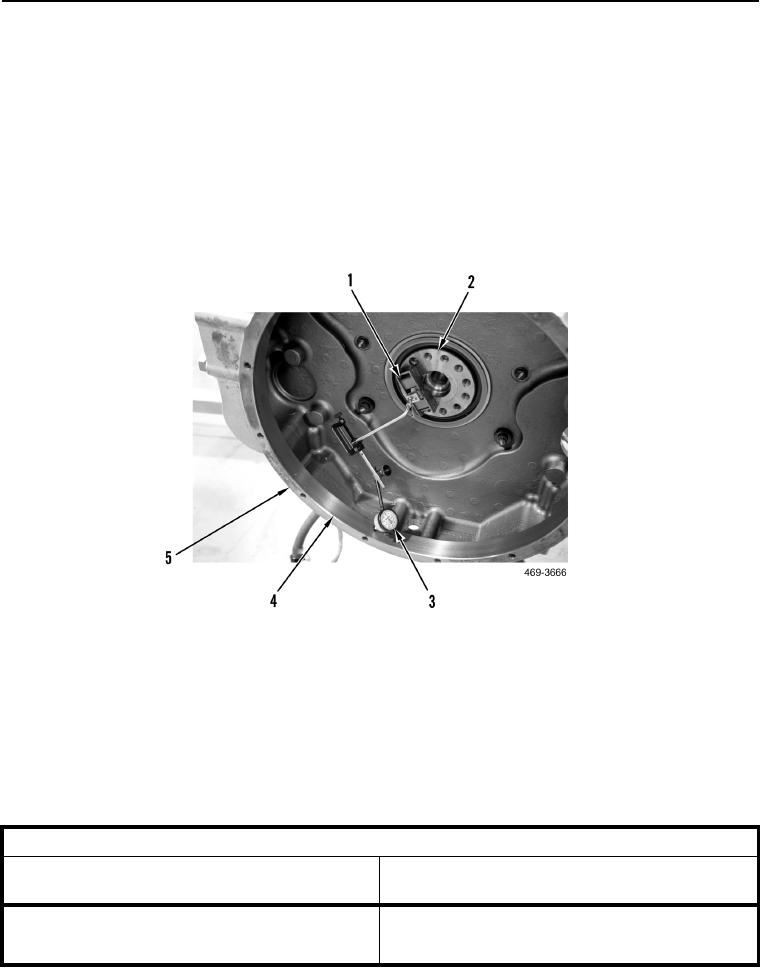
1. Install magnetic base (Figure 24, Item 1) and dial indicator (Figure 24, Item 3) on crankshaft (Figure 24,
Item 2).
2. Position dial indicator (Figure 24, Item 3) on inside face (Figure 24, Item 4) of flywheel housing flange
(Figure 24, Item 5) of flywheel housing. Set pointer of dial indicator to 0 inch (0 mm).
Figure 24. Flywheel Concentricity.
032
3. With assistance, rotate engine (refer to Manually Turning Engine in this work package).
4. Note reading on dial indicator every 45 degrees.
a. Calculate difference between lowest measurement and highest measurement.
b. Difference must not be greater than limit given in Table 2. If readings are greater than limits in Table 2,
flywheel housing is bent, replace flywheel housing (WP 0101).
Table 2. Limits for Flywheel Housing Runout and Alignment.
032
(TOTAL INDICATOR READING)
MAXIMUM LIMIT
BORE OF HOUSING FLANGE
(TOTAL INDICATOR READING)
0.010 in. (0.25 mm)
16.14 in. (410 mm)
0
0
17.63 in. (448 mm)
0.011 in. (0.28 mm)
0
0
Change 1

