TM 5-3805-263-14&P-3
DISASSEMBLY AND ASSEMBLY
CENTERSHIFT LOCKPLATE BUSHINGS
REPLACE CENTERSHIFT
LOCKPLATE BUSHING
Tools Needed
A
B
1P1832
Pulling Adapter
1
9S5558
Stud
1
1P544
Nut
1
3H467
Washer
1
5P3100
Pump Group (or electric)
1
1
9S9147
Installer Ring
1
7F9540
Puller Assembly
1
1
5F7353
Washer
1
5F7351
Nut
1
5P4776
Stud
1
5P4749
Adapter
1
9S8537
Installer Ring
1
start by:
a) remove blade shift bar
NOTE: Before disassembly check the clearance between
the snap ring on bushing and the shims. On the earlier
models the maximum clearance will be approximately
.014 in. (.356 mm). On the later models the maximum
clearance will be .350 in. (8.89 mm) between the snap
ring and shims.
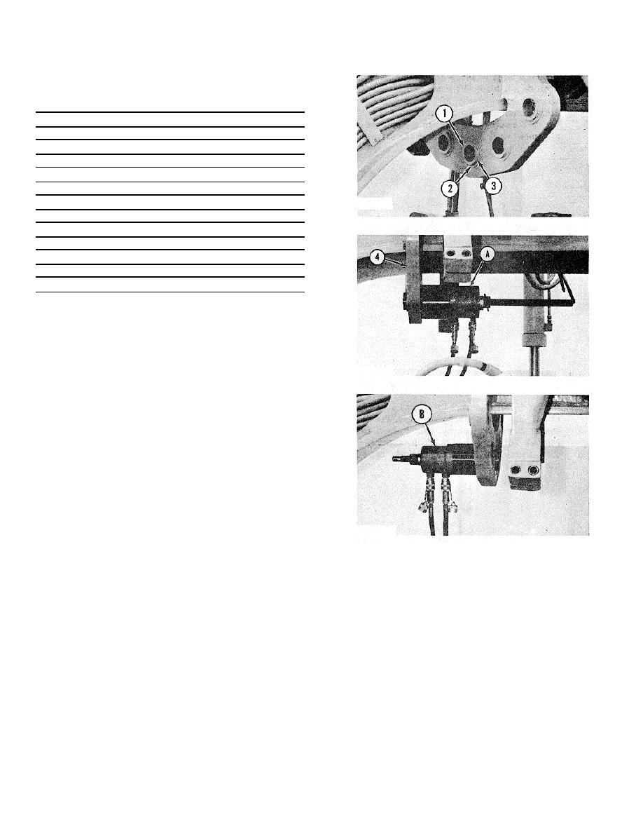
1. Remove snap ring (2) and shims (3) from
bushings (1).
2. Remove the bushings from lockplate (4)
toward the front of the machine with tooling (A).
3. Lower the temperature of the new bushings for
the earlier models to -70 to -900F (-57 to -
680C) on the later models lower the
temperature to -6 to -260F (-21 to -320C).
Install the bushing in the lockplate with tooling
(B). Install the bushing so it makes contact with
the shoulder in the lockplate.
4. Install the shims and the snap ring on the
bushing. The shims are used to get a .014 in.
(0.36 mm) maximum clearance between the
snap ring and lockplate on the earlier model
and a .350 in. (8.89 mm) maximum clearance
on the later models between the snap ring and
lock-plate.
NOTE: Some lockplate bushings can have replacements
made with the blade lift bar in position on the machine. It
will be necessary to put the blade lift bar and centershift
lock in a position away from the bushing of which a
replacement is to be made. end by:
a) install blade lift bar
3-200


