TM 5-3805-261-34
HYDRAULIC SYSTEM MAINTENANCE.
10-17.
Blade Lift Cylinder. (Sheet 5 of 6)
INSTALLATION
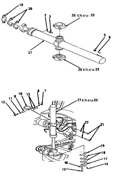
5.
Position items 25 thru 23 as an
assembly on cylinder (27, Figure
10-134).
6.
Install new performed packing
(6), elbow (5), new preformed
packing (3) and connector (2) on
cylinder (27).
7.
Attach hoist and sling to
cylinder (27).
8.
Lubricate ballstud and two
inserts (19) with clean grease
after surfaces are wiped cleaned.
9.
Install two shim(s) (20) and one
of two inserts (19) on cylinder
(27).
10.
Using hoist and sling, position
items 27 thru 23 as an assembly
(Figure 10-135).
11.
Install one of two inserts (19),
two shim(s) (18), cap (17), two
lockwashers (16), bolts (15) and
fitting (14).
12.
Check ballstud and two inserts
(19) for excessive clearance
between ballstud and surrounding
parts by moving cylinder assembly
(27). If ballstud or two inserts
(19) have become sufficiently
worn, excessive clearance may be
seen between ballstud and
surrounding parts. One or more
shim(s) (18 or 20) may be removed
to reduce unwanted clearance.
When removing two shim(s) (18 or
20), remove one shim from each
side of ballstud.
13.
Install four washers (22) and
bolts (21) in two caps (23).
Tighten four bolts (21) to 95
ft-lb torque.
Figure 10-135.
Figure 10-134.
Go to Sheet 6
10-101