TM 5-3805-261-34
HYDRAULIC SYSTEM MAINTENANCE. (cont)
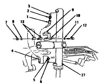
10-17. Blade Lift Cylinder. (Sheet 2 of 6)
REMOVAL
NOTE
All hose and tube assem-
blies must be tagged before
disconnecting to aid in
installation. Cap all hose ?
and tube ends to prevent
contamination.
The following is a mainte-
nance procedure for the
left blade lift cylinder.
The maintenance procedure
for the right blade lift
cylinder is identical.
1.
Disconnect hose assembly (1,
Figure 10-129) from left side of
front frame.
2.
Remove connector (2) and
performed packing (3) from left
cylinder (27). Discard preformed
packing (3).
3.
Disconnect hose assembly (4).
4.
Remove elbow (5) and preformed
packing (6). Discard preformed
packing (6).
5.
Remove nut (7), washer (8),
spacer (9), clamp (10), washer
(11) and bolt (12).
6.
Separate two clips (13) with hose
assemblies (1 and 4) from
cylinder (27). Two clips (13)
remain attached to hose
assemblies (1 and 4).
Figure 10-129.
Go to Sheet 3
10-98