TM 5-3805-261-34
FUEL SYSTEM MAINTENANCE. (cont)
3-25.
Fuel Injection Pump. (Sheet 13 of 16)
ASSEMBLY (cont)
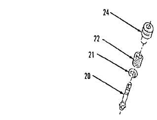
27. Position washer (21) on plunger
assembly (20) with flat side of
washer facing gear on plunger
assembly (20).
28. Install plunger assembly (20)
through spring (22) and into
barrel (24) until washer (21)
engages spring (22).
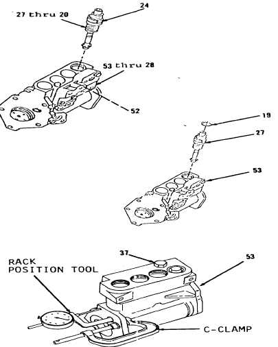
29. Aline items 27 thru 20 as an
assembly with slot in gear on
items 53 thru 28 180 degrees away
from groove in barrel (24, Figure
3-95).
30. Using extractor, aline groove in
barrel (24) with dowel (52) in
housing (53) and install.
Installation of remaining pump
assemblies is the same.
NOTE
Installation of pump assembly
is made easier by rotation of
camshaft lobe away from four
lifters.
31. Install new preformed packing
(19) on top of bonnet (27, Figure
3-88).
32. Measure rack (37, Figure 3-96)
travel. Install rack position
tools, contact pin and C-clamp.
Correct rack travel is 0.618
inch. A smaller measurement is
an indication of wrong
installation of items 27 thru 20.
Remove tooling and install
remaining items.
Go to Sheet 14
3-128
Figure 3-89.
Figure 3-95.
Figure 3-88.
Figure 3-96.