TM 5-3805-261-34
ENGINE MAINTENANCE.
3-7.
Timing Gears and Plate. (Sheet 6 of 9)
INSTALLATION
NOTE
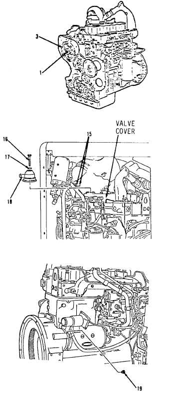
Before installing gear (3,
Figure 3-19), No. 1 piston must
be at top center (TC) of com-
pression. Perform steps 10
through 25 to insure proper
timing.
10.
Loosen two clamps (15, Figure
3-29).
11.
Remove bolt (16), washer (17) and
breather (18) from valve cover.
12.
Remove plug (19, Figure 3-30)
from flywheel housing.
CAUTION
Do not turn crankshaft
counterclockwise.
13.
Turn crankshaft clockwise (as
seen from front of engine) until
a 3/8-16NC bolt at least 2-5
inches long can be installed in
flywheel through plug (19) hole
in flywheel housing.
14.
Observe rocker arms for No. 1
piston through breather hole (18)
in valve cover. Check if both
rocker arms can be moved backward
and forward by hand.
15.
If 3/8-16NC bolt is installed and
both rocker arms move freely, the
No. 1 piston is at top center of
compression stroke.
16.
If both rocker arms cannot be
moved by hand, the No. 1 piston is
not at top center of compression
stroke. Remove 3/8-16NC bolt.
17.
Turn crankshaft clockwise 360
degrees (one full turn).
Go to Sheet 7
Figure 3-19.
Figure 3-29.
Figure 3-30.
3-43