TM 5-3805-261-34
ENGINE MAINTENANCE. (cont)
3-8.
Cylinder Block Liners. (Sheet 2 of 3)
INSPECTION
1.
Measure cylinder liner bore.
Maximum allowable diameter is
4.755 inches. If oversized, mark
for removal.
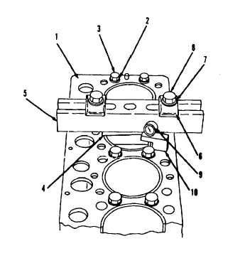
2.
Install spacer plate (1), 20
washers (2) a ten bolts (3,
Figure 3-34) in cylinder block.
Tighten ten bolts (3) evenly in
four steps of 10 ft-lb, 25 ft-lb,
50 ft-lb and 70 ft-lb torque.
Use two of 20 washers (2) with
each of ten bolts (3).
3.
Install adapter plate (4),
crossbar (5), two plates (6),
washers (7) and bolts (8).
Tighten two bolts (8) evenly in
four steps of 5 ft-lb, 15 ft-lb,
25 ft-lb and 50 ft-lb torque.
Measurement from bottom of
crossbar (5) to spacer plate (1)
must be the same on both sides of
cylinder liner.
4.
Assemble contact point, dial
indicator (9) and gage body (10).
5.
Adjust dial indicator (9) to
zero.
6.
Measure cylinder liner projection
as close as possible to four
corners of adapter plate (4) on
cylinder liner. Liner projection
must be 0.0012 to 0.0069 inch.
Difference between four measure-
ments on cylinder liner must not
be more than 0.002 inch.
Difference in average cylinder
liner projection for liners next
to each other must not be more
than 0.002 inch. Maximum
difference in average projection
for all cylinder liners must not
be more than 0.004 inch.
Go to Sheet 3
Figure 3-34.
3-48