TM 5-3805-261-34
FRAME MAINTENANCE. (cont)
16-2. Frame Separation and Connection. (Sheet 6 of 12)
REMOVAL (cont)
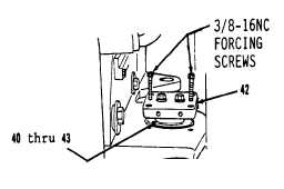
20. Install two 3/8-16NC forcing
screws in plate (42) and remove
items 40 thru 43 as an assembly
(Figure 16-10).
NOTE
Lift or lower rear frame with
forklift to remove any
pressure from pin assembly.
21. Remove two 3/8-16NC forcing
screws.
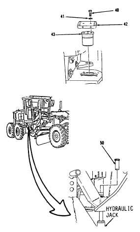
22. Remove two bolts (40),
lockwashers (41) and plate (42)
from pin (43, Figure 16-11).
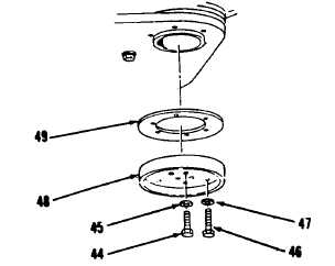
23. Remove four bolts (44), lock-
washers (45), six bolts (46),
lockwashers (47), plate (48) and
shim(s) (49, Figure 16-12). Tie
shim(s) (49) together and tag for
identification.
24. Using a hydraulic jack, remove
bottom pin (50, Figure 16-13).
Figure 16-10.
Figure 16-13.
Figure 16-11.
Figure 16-12.
Go to Sheet 7
16-8


