TM 5-3805-261-20
HYDRAULIC SYSTEM MAINTENANCE. (cont)
15-24.
Blade Lift Lines, Fittings and Hoses. (Sheet 9 of 10)
INSTALLATION (cont)
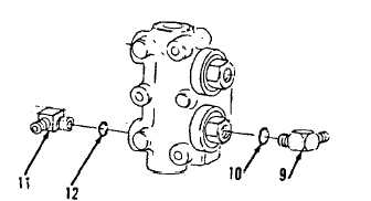
26.
Install items 12 thru 9 as an assembly
(Figure 15-83) on right blade lift check and
relief valve. Refer to paragraph 15-16,
steps 1 - 4.
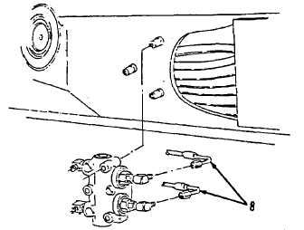
27.
Install two hose assemblies (8, Figure 15-
82) on right blade lift check and relief valve.
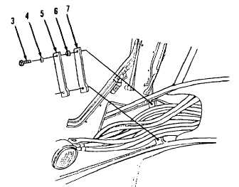
28.
Install clamp (7), two spacers (6), clamp (5),
two washers (4) and bolts (3, Figure 15-81).
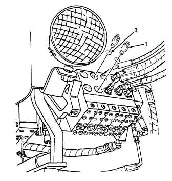
29.
Install two new preformed packings (2) and
connectors (1,Figure 15-80) to right hand
control valve.
Figure 15-80.
Figure 15-83.
Figure 15-82.
Figure 15-81.
Go to Sheet 10
15-124