TM 5-3805-261-20
HYDRAULIC SYSTEM MAINTENANCE. (cont)
15-24.
Blade Lift Lines, Fittings and Hoses. (Sheet 7 of 10)
INSTALLATION (cont)
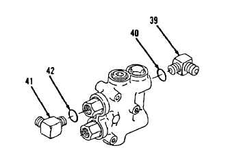
11.
Install items 42 thru 39 as an assembly
(Figure 15-90) on left blade lift check and
relief valve. Refer to paragraph 15-16,
steps 1 thru 4.
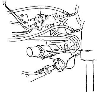
12.
Install two hose assemblies (38, Figure 15-
89) on left blade lift check and relief valve.
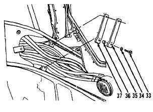
13.
Install clamp (37), two spacers (36), clamp
(35), two washers (34) and bolts (33, Figure
15-88).
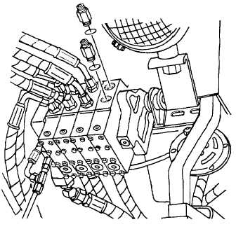
14.
Install two new preformed packings (32)
and connectors (31,Figure 15-87) to left
control valve.
Figure 15-87.
Figure 15-90.
Figure 15-89.
Figure 15-88.
Go to Sheet 8
15-122