
TM 5-3805-293-23-5
0313
INSTALLATION
000313
WARN I N G
Use extreme caution when handling heavy parts. Provide adequate support and use
assistance during procedure. Ensure any lifting device used is in good condition and of
suitable load capacity. Keep clear of heavy parts supported only by lifting device. Failure to
follow this warning may cause injury or death to personnel.
N OT E
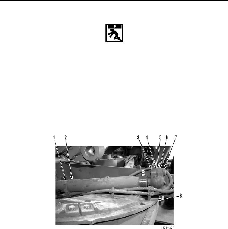
Centershift cylinder weighs 120 lb (54 kg).
1. Attach sling and suitable lifting device to body of centershift cylinder (Figure 6, Item 2).
2. Using lifting device, install centershift cylinder (Figure 6, Item 2) on circle assembly (Figure 6, Item 8).
3. Install cap insert (Figure 6, Item 3), shim (Figure 6, Item 4), cap (Figure 6, Item 5), washers (Figure 6, Item 6),
and two bolts (Figure 6, Item 7) on centershift cylinder (Figure 6, Item 2).
4. Install two clamps (Figure 6, Item 1) on centershift cylinder (Figure 6, Item 2).
Figure 6. Lower Centershift Cylinder Cap.
0313