
10
TM 5-3805-293-23-5
FIELD MAINTENANCE
-
BLADE/MOLDBOARD REPLACEMENT
0
305
Removal, Cleaning and Inspection, Installation
INITIAL SETUP
Personnel Required
Tools and Special Tools
0
0
Tool Kit, General Mechanic's
Two
0
(WP 0354, Item 83)
0
References
0
Bracket, Link, 1/2" 4,000 lb (1,800 kg)
(WP 0354, Item 13)
0
0
Hoist, Lever (WP 0354, Item 43)
Equipment Condition
0
0
Sling, Nylon (8 ft) (WP 0354, Item 65) (2)
0
Machine parked (TM 5-3805-293-10)
0
Wrench, Combination, 30 mm (S0824)
Articulation lock pin installed (TM 5-3805-293-
(WP 0354, Item 85)
0
10)
0
Lifting device (2,000-lb [907-kg]
Drawings Required
minimum capacity) (2)
0
0
TM 5-3805-293-24P, Figure 156
Materials/Parts
0
0
Rag, Wiping (WP 0355, Item 25)
Estimated Time to Complete
0
0
Cotter pin
1.5 Hr
0
0
Locknut (6)
0
Wood block (2)
0
REMOVAL
000305
N OT E
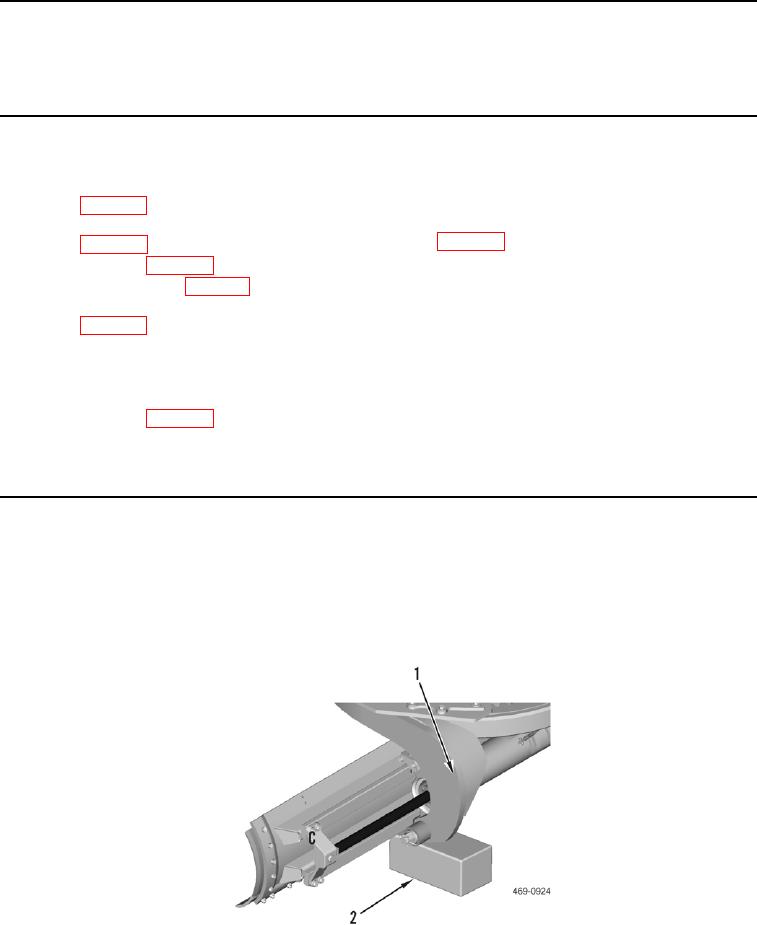
Position grader with sufficient side clearance for blade/moldboard removal.
1. Position two wood blocks (Figure 1, Item 2) under circle assembly (Figure 1, Item 1).
Figure 1. Circle Assembly Support.
0305