
TM 5-3805-293-23-2
0039
ELECTRIC STARTING SYSTEM TEST CONTINUED
00039
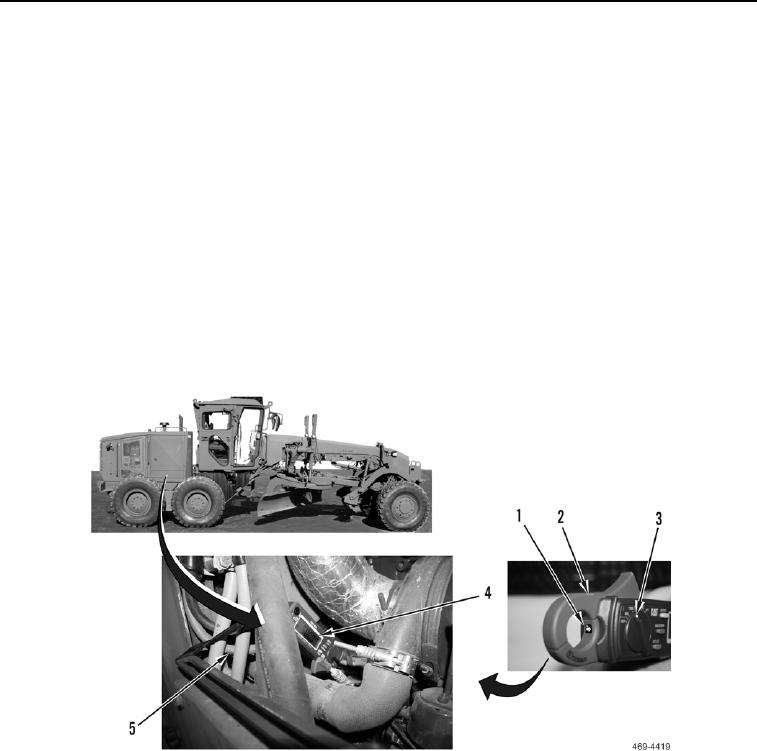
5. Set the dial on the ammeter (Figure 3, Item 3) on the 1200 DC amp scale. Press the zero button to zero the
meter. Make sure the Hold function is not ON (Hold will be indicated on display (Figure 3, Item 4)).
6. Connect clamp of ammeter (Figure 3, Item 2) around positive battery cable connected to starter motor solenoid
(Figure 3, Item 5) with the arrow on the ammeter clamp (Figure 3, Item 1) facing in the direction of current flow
(towards starter).
7. With an assistant, monitor and record the value on ammeter face (Figure 3, Item 4), while attempting to crank
the engine (TM 5-3805-293-10).
N OT E
Current specifications and voltages specified in Table 1 are measured at temperature of
80F (27C). When temperature is below 80F (27C), voltage will be lower through
starting motor. When temperature is below 80F (27C), current through starting motor will
be higher.
a. If current is less than 600 amps, starter and battery cables are OK.
b. If current is greater than 600 amps, proceed to step 8.
Figure 3. Starter Cable.
0039